Marine Flanged Angle Fire Hydrant GB/T2032-93 Type B/BS:
China Marine Flanged Angle Fire Hydrant GB/T2032-93 Type B/BS:
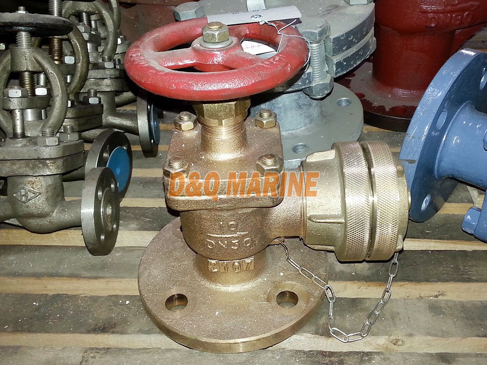
Marine Flanged Angle Fire Hydrant GB/T2032-93 Type B/BS is the angle hose valve for fire-fighting system in the vessels, also called as marine fire valve.
Technical Specification:
Design Standard: GB/T2032-93, CBM1107-82
Test Standard: GB600
Flange size as per GB569, GB2501. Also be as per JIS, DIN, ANSI, BS standard. The adaptor can be Chinese type, BS type, Storz Typa, ANSI type, Nakajima type.
| Nominal Pressure (Mpa) | Nominal Diameter (mm) | Applicable Medium |
| 1.0 | 40--65 | Sea water, fresh water |
Main Parts & Material:
Body-Bronze or Brass
Bonnet-Bronze or Brass
Disc-Bronze or Brass
Stem-Bronze
Seal Face-Bronze or Brass
Adaptor-Brass
Main Size List(mm):
Type A/B (Flange as per GB569):
|
DN (mm) |
Structure Dimension | Thickness δ | Flange | Bolt | hand wheel | Lift Range m | Weight(kg) | ||||||||||||||
| L | L1 | H1 | L2 | H2 | |||||||||||||||||
| A | B | A | B | A | B | D | D1 | D2 | d0 | b | n | Th. | Do | S | A | B | |||||
| 40 | 240 | 134 | 85 | 70 | 181 | 154 | 90 | 70 | 5 | 125 | 93 | 74 | 14 | 14 | 6 | M14 | 120 | 11 | 14 | 6.25 | 5.75 |
| 50 | 258 | 145 | 85 | 80 | 189 | 156 | 100 | 80 | 5 | 135 | 103 | 84 | 14 | 14 | 6 | M14 | 120 | 11 | 16 | 7.82 | 7.27 |
| 65 | 294 | 170 | 100 | 95 | 220 | 125 | 120 | 90 | 6 | 155 | 123 | 104 | 15 | 14 | 6 | M14 | 140 | 12 | 20 | 9.80 | 9.40 |
Type AS/BS (Flange as per GB2501):
|
DN (mm) |
Structure Dimension | Thickness δ | Flange | Bolt | hand wheel | Lift Range m | Weight(kg) | ||||||||||||||
| L | L1 | H1 | L2 | H2 | |||||||||||||||||
| AS | BS | AS | BS | AS | BS | D | D1 | D2 | b | d0 | n | Th. | Do | S | AS | BS | |||||
| 40 | 225 | 130 | 80 | 65 | 181 | 154 | 80 | 65 | 5 | 150 | 110 | 88 | 16 | 18 | 4 | M16 | 120 | 11 | 14 | 7.25 | 6.65 |
| 50 | 238 | 145 | 85 | 75 | 189 | 156 | 85 | 75 | 5 | 165 | 125 | 102 | 17 | 18 | 4 | M16 | 120 | 11 | 16 | 8.94 | 8.27 |
| 65 | 284 | 170 | 100 | 95 | 220 | 190 | 110 | 90 | 6 | 185 | 145 | 122 | 17 | 18 | 4 | M16 | 140 | 12 | 20 | 10.70 | 10.30 |
The size when working pressure is 3Mpa
|
DN (mm) |
Structure Dimension | Thickness δ | Flange | Bolt | hand wheel | Lift Range m | Joint | Weight(kg) | ||||||||
| L | H1 | H | ||||||||||||||
| D | D1 | D2 | d0 | b | n | Th. | Do | S | d0 | |||||||
| 40 | 62 | 90 | 326 | 5 | 125 | 93 | 74 | 15 | 14 | 6 | M14 | 120 | 11 | 11 | G1-1/2 | 7.6 |
| 50 | 75 | 95 | 353 | 6 | 135 | 103 | 84 | 15 | 14 | 6 | M14 | 140 | 11 | 14 | G2 | 9.8 |
| 60 | 82 | 115 | 416 | 7 | 170 | 132 | 110 | 17 | 17 | 8 | M16 | 160 | 12 | 18 | G2-1/2 | 12.6 |
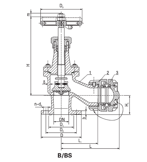
A/AS-Straight Type
B/BS-Angle Type